Lambda Switching Power Supply Updated June 18 2008
Welcome to your new switching power supply.
This documentation describes the use and modifications that can be implemented on this unit.
Download and print this information now. Do not rely on this link being valid at any time in the future.
Note that working with AC line voltages and line-powered equipment is dangerous business. You can hurt or kill yourself, and you can cause damage to property as well as endanger others. By connecting home made equipment to the mains, you may breach local city and state laws governing public safety, may void your home fire insurance policy, and may place yourself at risk of litigation. You do this at your own risk. By reading further, and using or modifying this power supply, you formally acknowledge that you are a licensed engineer or electrician who can legally work with AC power lines and line operated equipment. Just for the record, I, the person providing this information, am a penniless peasant living in the mountains of Nepal.
That said, let’s get to work.
You’ll
need to get a killer cord
( an AC cord with a line plug at one end and
stripped wire terminals at the other end -- If you're making one, make
sure the stripped ends are of unequal length, by a few inches, so the exposed
wires cannot touch by mistake.).
Steal one from an old toaster or
other broken appliance. Solder the wires to the AC line IN terminals on the
power supply, according to the photo below. DO NOT DRY-TWIST THE WIRES TO
THE TERMINALS –SOLDER AND INSULATE THEM! If you don’t know which are
the live and neutral wires in your house, check the links below.
http://en.wikipedia.org/wiki/Domestic_AC_power_plugs_and_sockets
NOTE: If you use a computer power cord or other cord based on the international wiring color code, BROWN = LIVE, BLUE = NEUTRAL, and GREEN/YELLOW STRIPE = GROUND. For standard power cords in the USA, BLACK = LIVE, WHITE = NEUTRAL, and GREEN = GROUND.
North American plugs use a wider spade (wider slot) for the NEUTRAL wire, and a narrower one for the LIVE wire.
http://www.epanorama.net/links/wire_mains.html#mains
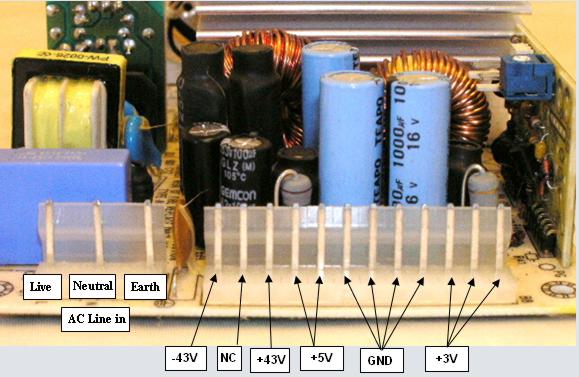
This is the pinout of voltages at the supply’s header: (you may leave the earth unconnected if you use a 2-wire cord)
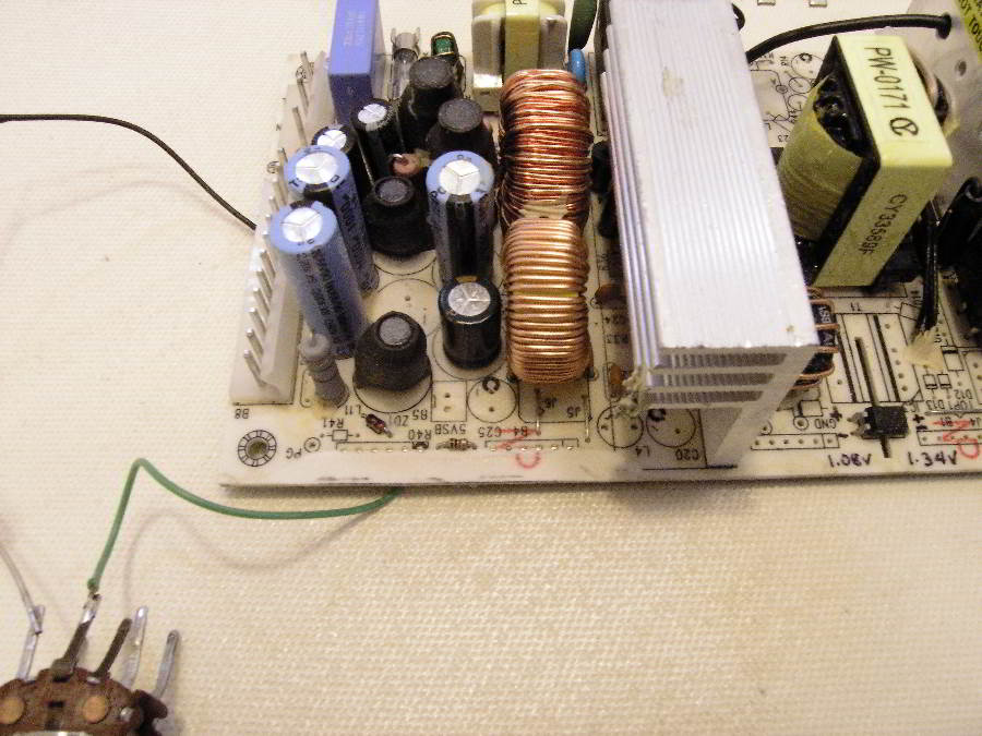
Place the power supply on a non-conductive surface. A sheet of paper may do.
Note that the SMPS full-wave rectifies the AC line, which means there are voltages of 165V and 330V flying around this board, if your mains voltage is 120V and 220V, respectively. This is Direct Current, which is much more dangerous than AC. It can give you a jolt hard enough to cause you to knock other things around on the bench, possibly causing a bigger fiasco.
Check the picture two images below (the Roadmap). Areas 1,2,3,and 4 contain the highest voltages. Do not just pick up the board with your hands to move it while power is applied. Think before you touch. The larger heat sink is grounded to the SMPS primary ground. This is the negative side of the full-wave rectified AC line, which is at high voltage potential with respect to BOTH mains wires. Although not particularly recommended, in a bind, you can grab the board by the smaller heatsink to move it around, since this is on the secondary side.
The secondary is completely isolated from the primary, but note that the secondary high voltage rails have almost 100V between them, which can also give you a jolt. You really have no business touching the board while it's powered, do all your touching with the power off. After shutting off the supply, wait at least 10 seconds before touching it, as the energy in the reservoir capacitors does not disappear immediately.
IMPORTANT:
Do not connect to this power supply any test equipment, including oscilloscopes, bench power supplies, voltmeters, etc, which are not completely isolated from the mains line. It may be tempting to try to view waveforms on this board with a scope. All oscilloscopes that I know of have their grounds tied to the AC line ground (safety regulations require it). You will cause a short unless you power your test equipment through a line isolation transformer (120V to 120V or 220V to 220V). Make absolutely sure the transformer you use is a true isolation transformer, and not an autotransformer. Alternately, you may chose to power the switching supply through an isolation transformer instead, however this would require an isolation transformer with a 300W capacity to fully test the supply. Conversely, most oscilloscopes ( with CRT) only use about 40W, less if with an LCD screen. You can make an isolation transformer which will be useful with many other things (see Appendix )
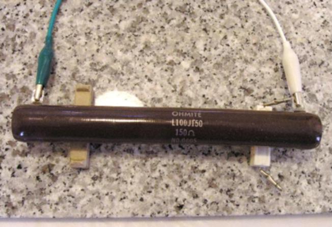
Switching power supplies cannot operate unloaded. (see Appendix for explanation). This supply has a minimal required load of about 3-5 watts for operation. If your application does not draw any current from the 5V or 3V supplies, you will need to permanently install a load resistor of 10-15 ohms (5 Watt) on the 5V output (you might as well solder it onto the 5V pins). The supply will not come on without this load present.
Once you’ve done that, you can place a voltmeter across the +43 and -43V pins (use alligator patch cords—watch out for the clips shorting neighboring pins), and turn on the power. You should read a voltage between 86V And 100V. Carefully turn the blue trimmer potentiometer (upper right in the photo above) from one extreme to the other, and note (write down) the minimum and maximum voltages obtained. Divide by 2 for the individual rail voltages. You should get something between 43V and 50V x2. We try to specify the voltage at the lower end of its range to more realistically estimate these values while they sag under load.
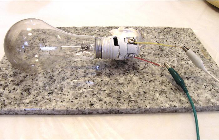
With the voltmeter in place, connect a dummy load across the two rails (from V+ to V-), in parallel with the voltmeter. A first dummy load might be a 100W household light bulb. Use a socket for the bulb and be sure it is sitting on non-combustible material, a ceramic or porcelain dish for example. Turn on the supply, read the voltage and leave it on for 5 minutes. Wearing latex gloves, touch each heatsink and confirm that they are not too hot to touch. The 100W bulb exercises the supply at about 55W output. If your mains voltage is 220V, the 100W bulb will only draw about 22W. You'll need to adjust the dummy loads for your particular voltage. Turn off power, and replace the bulb with a 150W or 200W bulb and repeat the test. The 200W bulb will test the supply at 120W output. For higher power tests you will need powerful resistive loads of 40 ohms to 150 ohms. To test at full power, a 200W 40-45 ohm resistor is required. If this is not available, it can be made from a combination of several power resistors in series/parallel combinations that amount to 45 ohm or so. In a bind, a lower power resistor --100 W or 60W-- may be used, provided the load test is only carried out for a brief period, say 10 – 20 seconds.
Warning! All dummy load tests ( and particularly those at 200W ) cause the load to get very, very HOT. It could melt, burn, char, or set fire to whatever material the dummy load is on. This is no joke, you absolutely need to take precautions to place dummy loads on safe surfaces. Metal is not recommended, since it can cause random and unexpected shorts. The best materials are glass, ceramic, porcelain, concrete, stone, mica, or asbestos. Do not let the dummy load lie flat directly on a surface. Rest it on two heat-resistant wedges, such as two power ceramic resistors, so air can circulate underneath it. Do not walk away and leave a dummy-loaded circuit unattended.
A dummy load test is a much more rigorous test than what an audio amplifier will put the power supply through. Audio signals place lesser demands on a power converter than continuous-dissipation tests.
If your application can accept the lowest voltage you have obtained during the trimpot rotation test, then your testing stops here; you’re ready to deploy your new SMPS solution.
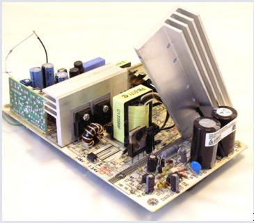
Roadmap - Finding your way around the Lambda switching power supply
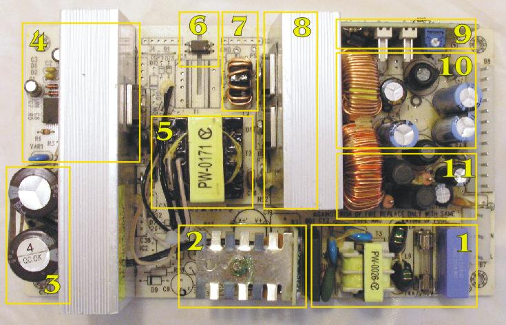
Modules are numbered in the order in
which the power travels through the board.
1. AC input filtering. RFI, differential mode filter, common-mode filter choke and inrush-current limiter. Full wave bridge rectifier.
2. Voltage doubler / crowbar (safety shut down))
3. Reservoir capacitors.
4. PWM controller, UC3842 current-mode controller IC, and associated circuit, +power MOSFET.
5. High frequency transformer.
6. Optical coupler
7. Saturable inductor (magnetic amp).
8. Secondary side rectifiers
9. Analog error signal conditioning board
10. 5V and 3.3V secondary filtering
11. High Voltage rails filter components. Coupled cross-regulating inductor.
If your application needs supply voltages that are just 1 or 2 volts lower than the lowest trimpot voltage, it may not be worth modifying the supply for that. The voltage will sag under load ( by 1-2 volts) anyways and furthermore, placing a common 3 A silicon diode (or two) in series with each rail can lower the voltage by 0.6 to 1.2 volts.
If you decide you want to carry out the voltage lowering modification, note the following:
1. The mod is not easily reversible.
2. The mod will produce a voltage adjustable between 38.5 and 42 volts at each rail. (it is possible to get higher voltages as well, up to 60V x2, see Appendix)
3. Actual voltages obtained may vary depending on the particular unit.
4. The minimal load (the power resistor placed on the 5V rail to get the unit to turn on and stay on) will have to be moved from the 5V rail to the 39V rails. A resistor of the right value to draw 3-5 watts from the high voltage rail needs to be permanently connected between the V+ and V- rails. This value is 2.4K, 3W for an output voltage of 39.2V and 1.3K 5W for an output of 38.2V. You will remove the load resistor from the 5V rail. It becomes increasingly difficult to obtain voltages lower than about 38.2 V, since the value of the idle load resistor needs to decrease exponentially, and it ends up drawing too much power.
5. Regulation of the +/- 39V outputs will be better than before the mod. This is because the mod changes the way the regulation mechanism senses the output voltage, causing it to sense the +/- 39V lines directly, which it was sensing indirectly before.
What we'll do
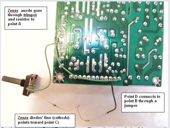
The mod involves adding a 5K-10K potentiometer (or trimmer), fixed resistor (500-900 Ohm), and two Zener diodes ( 36V ). All these parts are connected in series. Their order does not matter so long as they are connected end-to-end. Two zener diodes are used, because the 72-74V voltage reference required is not obtainable with a single zener. 72Volt is not a standard Zener voltage. (if you can get a 72-74V zener, by all means do so.) The two diodes must be connected together with the same orientation –both having their stripes (cathodes) pointing in the same direction. Look closely and understand the pictures that follow before making the connections. Below is a rough idea of what the mod looks like. This is for an initial test only, all components must be neatly and safely secured on the pc board afterwards.
You need to plan where these extra parts will go in the final installation. To make the mod space-efficient, you should consider attaching the extra parts to the topside of the board, with epoxy or silicone glue, in a way that keeps them isolated from other topside components. Lead length is not critical, so you can route the wires in whatever way makes the final result neater.
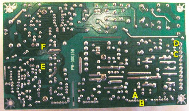
In preparation for modifying the power supply, flip over the unit and look over the bottom of the board. Place it as in the photo below and locate the 3 areas where we will make modifications. The work required on the unit itself involves cutting two copper traces, making 4 solder connections to the bottom of the board, and soldering a resistor in parallel with an existing resistor (on top or bottom of board). The circuit nodes we will use to make modifications are labeled A through F.
STEP 1.
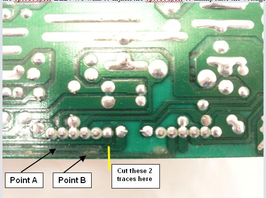
The low-voltage modification starts with the slicing of the 2 traces shown. This image is from under the analog controller daughter board (the one with the blue trimpot.)Use a craft blade or a Dremel grinding tool to cut the 2 copper traces. It is important that you locate and cut just the two copper traces closest to the edge of the board, no more, no less. Outer trace is B, inner one is A, do not get them mixed up. Once cut, scrape away some green varnish off the two copper traces, in the direction pointing to the LEFT in the picture below (towards the optocoupler). What we’re doing: isolating points A and B, which lead to the optocoupler LED. We want to hijack the optocoupler to manipulate the voltages that are fed to it.
STEP 2.
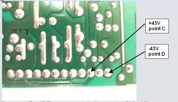
Locate points C and D which are underneath the output pin header of the power supply. We will solder thin leads of wire to each of the points C and D.
What we're doing: We'll use the + and - 43V rails, in series (about 76-90V) for feedback loop sampling. We will scale this voltage, by passing it through a zener of about 70-78 V, which will drop most of the voltage and leave us with only a few volts out, to drive the LED of the optocoupler. The LED will be driven through a current limiting resistor. Since a 1 V change in the 80V line results in a 1V change in the resulting low voltage (3-5V), we’re amplifying a 1% change into a 20-30% change. This makes the regulation very sensitive and responsive to output load demands.
STEP 3.
Connect points B and D with a jumper. Cut the jumper wire to size so it has no slack. Keep solder points at the ends of wires small so they don't touch anything around them. Use tiny amounts of solder flux to ensure perfect solder flow and joints.
Connect point A to point C through the following, all in series: a 500-900 ohm resistor, a 5-10K trimpot, and a 72V zener diode. Since 36V zeners are common and 72V zeners are not, two 36V will be used in series. Black stripe of the zener goes away from point A and towards point C ( the + supply rail). Solder this entire string of parts in series, leaving the jumper wires long enough to allow some slack (we'll trim them later). For the potentiometer, you'll use the center pin and one of the side pins, doesn't matter which one.
What we're doing: This anchors the cathode of the optocoupler LED to the negative supply rail, and the anode to the positive rail minus 72 volts. Some additional voltage is dropped across the trimpot and resistor, to limit LED current and control it's brightness. This brightness ultimately determines the width of the Pulse-Width-Modulated square waves fed through the transformer, and determines the level of the output voltage.
We have replaced the output voltage sensing circuit, so that, instead of sensing the 5V and 3V lines, it is only sensing the +/- 39V lines.
STEP 4.
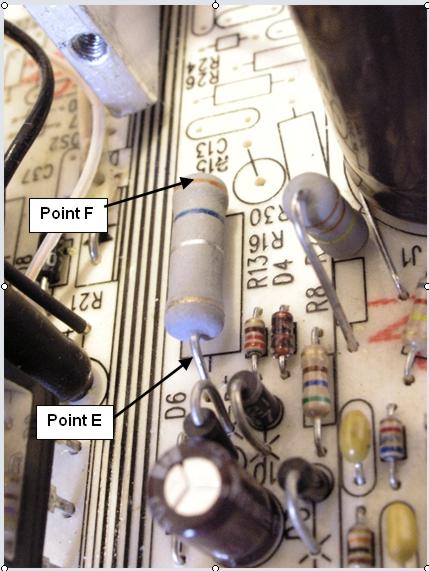
Locate points E and F. They are the terminals of power resistor R16, a 0.36 ohm power resistor lying flat next to the larger heatsink, behind the two large brown electrolytic capacitors. We will parallel a 0.3 - 0.5ohm 1Watt resistor with it, by soldering on the underside (ugly but quick), or by soldering it topside right on top of the existing resistor. For the latter solution, you need to lift the heatsink to gain access to the area.
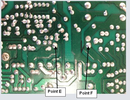
Points E and F connected through an external power resistor ( .3 to .5 ohms), the ugly way.
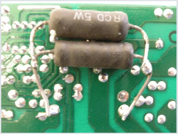
What we're doing: R16 is the current sense resistor on the primary side. (its label is printed on the pcb). Since dropping the output voltage should allow us to get more current from the secondary (to maintain the same power output), we need to tell the primary sensing circuit to allow that higher current. We do this by lowering the value of this resistor. Doing this step with the power resistor is optional. If you skip it, the power supply will give you the same current at lower voltage (39V) as it does at the higher voltage (49V) which is 2 A continuous. When you try to draw more, it turns the output off rather than let the voltage sag. This protects both the power supply and its load from current overloads. Lowering this resistor rises the point at which the supply goes into OCS (over current shutdown). Making this resistor too low can cause the supply to overheat. Under normal operation neither of the heatsinks will get too hot to touch.
Lifting the heatsink after removing two screws on the pcb bottom and one screw through the power MOSFET. (you can use long nose pliers to initially turn the MOSFET screw if a screwdriver won't fit.) Now you can solder the additional resistor in parallel with R16, right on R16’s leads. Trim the leads of the new resistor so it piggybacks just above R16.
Lastly, before being able to use the supply, you will need to solder a 1.5K (or close) power resistor between the + and - high voltage rails to act as the new idle load. You will remove the resistor used as an idle load on the 5V line.
You're done!
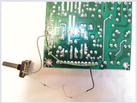
This is what the initial mod may look like:
![]()

This sloppy wiring may be ok for a test, to confirm that all works correctly, but for longer term use, it is imperative that leads be shortened, insulated, and all components anchored sturdily to the pc board, with epoxy or other void-filling glue, preferably in a vacant space on top of the board. If future adjustment of the output voltage is not needed, you can set the trimmer to the voltage needed, then measure it's resistance with an ohmmeter, and replace it with a fixed resistor.
You are ready to test the supply.
Recheck all wiring, since errors at these voltages can be catastrophic, not to mention spectacular.
If at all possible, take the following precautions: Connect the AC line to the supply through (1) a fuse holder holding a 2A fast-blow fuse, and (2) a light bulb socket, holding a 100W bulb. This allows the circuit some chance of surviving if something was wrong with your wiring.
Connect a voltmeter between the + and - high voltage pins, and set it's range to 200V. Set the potentiometer we added to it's midpoint rotation. Turn the power supply on and watch the voltage. It will take a couple of seconds to come up. Let it run for a minute without touching anything, to confirm that no smoke comes out of anywhere. Turn the potentiometer slowly in one direction, then the other, and watch the voltmeter. In the direction which causes a drop in voltage, you may reach a point, past which the supply stops working. The voltage will decrease to 76 volts or so, then the voltage will become erratic. Do not try to leave the potentiometer at the lowest possible voltage setting at which it will operate. It may be able to sustain operation at that voltage when it's running, but may not be able to START with the potentiometer at that position. Once you've determined the lowest voltage point, back down on the pot till the output rises back by about 0.2 to 0.5 Volts, to allow reliable starting.
Idle load optimization.
If the power supply will be used to power a Class B audio amp, is it possible that the quiescent current drawn by the load (with no signal input) may be sufficient to constitute a suitable idle load, allowing you to remove the power resistor that was filling that purpose, or at least to reduce its current (increasing its value). Many Class B and AB power amps draw 50 to 100 mA of quiescent current. Determine your situation experimentally. You should use the largest possible idle load resistor that will allow the supply to start reliably. This means connecting all amplifier loads to it, adjusting their quiescent current, and then gradually reducing the idle load current (increasing R), until the power supply no longer starts. Then back off 10%. In many cases you may find the amplifier quiescent current is enough to provide idle load for the supply without the need for a dummy resistor.
Regulation Performance
Switching power supplies do not have as tight a load regulation as linear ones. In the world of linear regulators, 1% and 0.1% voltage regulation are common. Of course the price paid is in heat dissipation and energy waste. SMPS's on the other hand, will commonly specify load regulation figures of 5% or 10%. Not that's it's impossible to match linear performance with a switcher, but in most cases, it's not worth the added complexity and cost. An SMPS still excels at line regulation, and can usually beat comparably priced linears, and transformer/rectifier/filter capacitor setups hands-down when it comes to power line 60Hz ripple.
Out-of-the-box, the Lambda SCS200 has a load regulation of 3% on the 5V line. This is the line the switcher was designed to regulate best. On the high voltage rails, regulation is 8%.
The 8% load regulation figure of the SMPS means that at 48V rail voltage, the continuous rated current (2A) will cause a drop of 3.84V in the rail voltage, bringing it to just over 44V. At 3A peak current draw, the drop is about 10%, or 4.8V, leaving you with rail voltages of 43V. This is the reason why I often refer to this as a 43V supply, even though its manufacturer labels it as 48V. I lean towards worst-case specs.
Now, sampling the 39V lines directly into the optocoupler, without going through the voltage summing/scaling board, improves regulation and response on the 39V lines, no doubt about it
Although adequate for most purposes, regulation performance can be improved, however. (see below)
Increasing regulation tightness
If you don't like that 10% load regulation figure, you can better it. You can lower it to as little as 1%, which clearly rivals any linear regulator. It involves changing a resistor and a capacitor value on the SMPS board.
That's the beauty of switching supplies. You're not locked into a set of specifications as you are with a toroidal line transformer and filter capacitor. You can pretty well dial your own numbers for some of the key parameters if you know what you are doing. You just need to do it safely.
So, how do we do this?
You locate resistor R5 and capacitor C8, first on the schematic, then on the PC board. They are found right next to pins 1 and 2 of the UC3842 IC, between the chip and the heatsink. You unsolder them. You may need to first straighten the pins of R5 on the underside of the board, by prying them up with a tiny screwdriver, to make removal easier. You then replace a 35-45K resistor for R5, and a 0.01 to 0.033uF capacitor for C8. As always, check for solder bridges after your work.
Can we really get something for nothing? What are we trading off?
We're not really trading off anything, but we are putting additional stresses on the MOSFET and power transformer. Remember that the supply was designed for 2A (or 200W) continuous output. Audio amplifiers are not continuous loads. When they draw an average of 2 amperes, they may draw 1 ampere 80% of the time, and 4.5 amperes 20% of the time (or something close). By stiffening the regulation, we're making greater demands of the MOSFET and the power transformer during those brief high current excursions. So long as the average power still stays within the 200W limit, and the peaks do not go over 300W we're OK. What you should NOT do, is use a supply modified as above to implement a lab power supply, which will be called on deliver a constant and sustained power over 200W.
Audio signals' high peak-to-average power ratio is the key that enables us to optimize this supply for audio and get a lot of muscle out of it.
What did we do?
With the above mod we changed the error amplifier's feedback components. Also known as the compensation network, the resistor and capacitor we changed constitute the negative feedback loop of the error amplifier. They determine how sensitive the controller is to changes in output voltage, and how quickly it will respond to these changes. By increasing the resistor value, and decreasing the cap value, we increased the gain of this amplifier. We dialed a more aggressive response, and increased the speed of this response. Do not alter the values of these components to a greater degree than indicated, or instability may result.
Because the Lambda was overengineered by its designers, its PWM operates well below the 50% duty cycle limit of a forward converter.
With the above mod, you are bringing it to about 40-45% duty cycle, so make sure you do not increase the error amp gain further than indicated. This can undermine the supply's stability when responding to a step-change in load demand. Step-changes are common in digital loads, but not in audio loads.
Shielding the power supply.
A metal enclosure is recommended to minimize EMI and RFI interference to neighboring equipment. Ii is always a good idea to shield a switching power supply from the circuits it powers to avoid harmful interference, especially with digital circuits. If you find it too difficult, expensive or impractical to provide a metal shield around the supply, consider the following solutions, often employed by commercial designs. A plastic box around the supply, with self-adhesive copper foil applied over it. Solder a lead to the copper (before applying it to plastic) and connect to a common ground pin. In lack of copper, aluminum foil, glued over a plastic box will do. Ground connection to the foil is made with a screw and nut. Laminated aluminum-plastic flexible film, forming a cage around the supply can also work. A screw-and-nut fastener through the laminate, in contact with the aluminum core is needed to make a ground connection.
Power requirements for Audio Amps
Class B and AB audio power amps have a nominal efficiency of 66%. This means that this power supply can power an amplifier of up to 133W. The amp will waste the remaining 67 Watts as heat. This is what would actually happen if the amp were playing a steady tone of 1KHz at maximum power. But that's not what happens in real life. Audio program sources tend to have a very high peak-to average power levels. The brief transients of a bass drum can be 2 to 4 times higher in amplitude than the rest of the music. This power supply can provide up to 3 amps per rail during such transients (after the mod). This amounts to a maximum power of 300W and a power amplifier rated at 200W. It is noteworthy that no Amp can deliver 200W into 8ohm loads with 45V supply rails, but it can deliver this power into 4 ohms. However, if the mod uses a 30K resistor for the adjustment trimpot, giving supply rails of 60V, then 200W into 8ohms become possible.
A P P E N D I X
1. Why does the power supply need a load to operate?
Unlike simple power supplies using 60Hz transformers and rectifiers, switching power supplies have additional circuitry which takes programmed decisions during it's course of operation. This circuitry needs itself power to operate, and it cannot use the 120V line voltage for this, it needs a low voltage DC. Where does this power come from? This power ends up coming from an additional secondary winding on the main power transformer, called the AUX, or auxiliary winding. The voltage from this winding is rectified and filtered and provides between 10V and 20V to the Pulse-Width-Modulator controller circuit. But the modulator circuit monitors the user's load and adjusts the width of pulses fed through the transformer depending on load demands. If a lot of current is demanded, pulses are wide, to transfer a lot of power over to the secondaries. If load current decreases, pulse width HAS to decrease; if it didn't, the output voltage would become higher than it's supposed to be. If load current is very, very low, the width of pulses becomes exceptionally narrow (needle pulses), and if the load draws no current at all, the pulses essentially almost disappear, since the reservoir capacitors on the output rails maintain their charge level with very little refreshing. Any pulses sent into the transformer would send the rail voltage up past its regulated limits.
But there is the conundrum:
needle pulses or absent pulses don't produce sufficient voltage on the AUX secondary winding to maintain operating voltage to the controller. So the controller stops working. Therefore the need for a minimal idle load to keep the controller running.
2. What have we done to the other voltages in the power supply with this mod? Have we lost any functionality?
This switching power supply was intended for microprocessor controlled jukeboxes. These are systems that contain both a high power audio amplifier, to play music, and digital microprocessor circuitry, to retrieve, buffer and queue the MP3 music from hard disk stores, and manage the user interface. The audio side needed dual high voltage rails, and was not too picky about regulation. The digital side required 5V and 3.3V and absolutely needed these voltages to stay within a 5% regulation window. (i.e the 5V really had to stay between 4.75 and 5.25V otherwise stuff would stop working). So the power supply needed to sample the voltage at all four outputs, and assign a different weight to each output, which would determine how closely that output would get regulated. The daughter board standing vertically to the side (with the blue trimpot) did that. It combined all four output voltages, with different weights, into one signal which drove the optocoupler. We bypassed all that, and fed the optocoupler a sample of only the voltage we are interested in, the high voltage rails. That daughter board is now unoperational. It can be removed altogether now, and the power supply wouldn't know the difference. You may in fact want to remove it to use the space for the extra mod components.
The 5V rail still puts out 5V and is still regulated --by virtue of being inductively coupled to the dual 48V rails through the toroidal transformer with different colors of wire. It's regulation is not as stiff as it was before, however we had to make some choices. As for the 3.3V line, it tracks the 5V line, since it's derived from it, through the saturable inductor ( # 7 in the Roadmap ). If you don't need the 3.3V output, you can remove it's associated components outright, and it wouldn't affect the operation of the remaining voltages one bit. These components are in group 10 (roadmap), specifically, the toroid closest to the top, and the 3 cylindrical parts directly to the right of it: 2 electrolytic capacitors, and one slug core inductor. The dual fast-recovery rectifier in the upper half of group 8 as well as the saturable inductor (7) can go as well. So you have a power supply that's more useful than it was before, and a handful of parts left over. Something to tell your friends about.
3. Can I get higher voltages?
Yes, but be careful. There are two watch-outs in doing so. The first is the primary current sensing mechanism. We've just numbed it a little by adding a resistor in parallel with R16, earlier. This was ok when you're looking for lower voltages, but dangerous when you go to higher voltages. You need ensure that you don't draw more current than is safe by way of fusing on the rails. I would use 3 A fuses if going up to 60V rails. Not that the supply would be destroyed at 3Amps, but operating it for extended periods at above 2.5A may cause it to overheat, possibly leading to thermal failure somewhere. You can parallel more than one supply if you need more current anyways. The second watch-out is that the electrolytic capacitors on the HV rails are 63V rated. This kind of places a 60V upper limit on the voltage you can get out of this rail (you may of course, upgrade the caps). Note that regulation becomes worse as you go up in voltage, because the pulse width approaches its maximum of 50% as you draw 3 Amps. This is a forward topology converter, limited to 50% duty cycle.
The potentiometer (trimpot) used earlier in the mod was specified at 5K to 10K. You can use a higher value for this pot. For every 5K increase in potentiometer resistance, you will gain an additional 5V of ceiling on each the high voltage supply rails. The maximum you should try is 30K, which provides a maximum rail voltage of +/- 60V
I am broadly disclaiming any responsibility for what you do in the course of hacking this power supply, but particularly, I am alienating myself especially from anything you do where higher voltages are involved. I am only providing this information in the spirit of scientific discovery and communication.
4. Removing the Analog daughter board.
The Analog daughter board (where the blue trimpot is located) is no longer functional after the mod. Unless you have serious concerns that you may wish to reverse the mod at some point in the future, it is perfectly safe to remove this board. Since it is very difficult to de-solder this part intact, removal is most likely by destruction. It can be sawed off from its base using a Dremel grinding tool or similar. Just be very careful not to hurt anything else on the board while cutting. And not to send metal dust flying into other areas of the power supply.
The extra empty space is an ideal location for the mod components. They can be glued in place, using care that they don't touch anything else on the board. Since the 3.3V output is most likely not used either, now is a good time to clear up even more space, and remove it's associated components (see earlier).
5. This requirement for an idle load resistor is clumsy and annoying. Isn't there a way around this?
There are two ways, neither of which is very simple.
The lower voltage you want at the output, the more you are starving the controller's AUX voltage, so the greater load (lower R) you need to use for idle load resistor, and more heat generated. You need to either use a controller IC with lower voltage requirements (change the IC), or supply its voltage requirements from outside the unit (supply it 15V at 20mA from another source). These options allow you to lower the voltage by a few volts below 38V, and reduce or eliminate the need for minimum load.
The first involves replacing the PWM controller, an 8 pin DIP IC. You can replace the UC3842 with a UC3843 or UC3845. The existing chip has a UVLO (Under Voltage Lock Out) of 10V. This means, whenever the AUX supply falls below 10V, the chip disables the outputs. The alternative chips are identical to the UC3842, but have a UVLO 0f 7.9V. This allows a lower idle load, (about half the power), and lower output voltage, before the AUX supply falls too low for operation. The work consists of de-soldering the 8-pin IC, and soldering in it's place, NOT the new IC, but an IC socket, so as to never have to repeat this procedure. Desoldering multiple pins can be done by using a solder sucker to remove all the solder at each pin, then gently moving each pin with a long nose pliers on the bottom of the pcb, so they can break free from the edges of their holes. Another option is forming a very large blob of solder on the pcb bottom, which touches all 4 pins on one side of the IC. A small screwdriver on the top side prys the IC away from the board on the heated side. Repeat the process on the opposite row of pins. Pry the IC out a little bit each time, till it breaks free. You may purchase the UC3843 / 3845 from Digi-Key and other distributors.
Replacing the IC is, in my opinion, an insane modification, and you would only do it to prove a point.
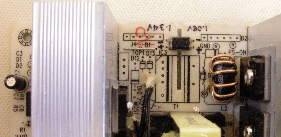
The second option completely eliminates any need for idle loading of the supply. It involves using a second, small power supply, providing 12-25 Volts at 15-20 mA. This supply will provide the AUX voltage needed by the controller circuit, without need for this circuit to rely on self-generated power. This solution is particularly attractive if you use several switching supplies in the same enclosure and you can power them all from the same AUX supply. The current required will be 20mA per SMPS served. This is still a very small power requirement, and can be obtained from some of the smallest wall warts. Below is a picture showing at which points you may connect an external AUX supply. One option is to connect directly to pins 5 and 7 of the controller chip. PIN 5 is GND and PIN 7 is V+. A neater approach is to connect to the solder pads intended for header block B1 on the illustration below. Locate header B1 just left of the optocoupler. It is a long rectangle with holes for 6 pins. First pin on the left is PIN 1. Number the pins in order from 1 to 6 to the right of pin 1. AUX V+ goes to PIN 1, and AUX GND goes to PIN 5.
IMPORTANT: if you attempt the above, note that AUX GND, the primary side ground, is the same potential as the negative side of the full-wave rectified AC mains. Do not touch this ground, and do not connect any external supplies here which are not completely isolated from the mains.
Yes, it may seem rather silly to have one power supply to power a second power supply, but if you work long enough with switching power supplies, you get used to it. Many larger SMPS's (1KW and above) have a small 60Hz transformer right on the pc board to supply their AUX power. It still keeps the overall size, weight, and efficiency of the solution much more advantageous than its linear 60Hz equivalent.
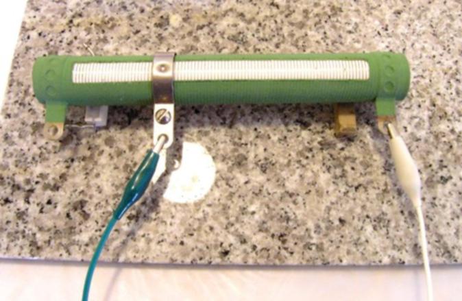
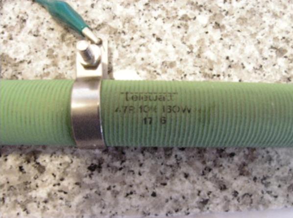
6. Examples of dummy loads:
7. FILTER CAPACITORS ON THE POWER AMP SUPPLY LINES
The amount of capacitance that can be added on the outputs of of an SMPS is limited. You cannot go crazy and add tens of thousands of microfarads on the supply rails, like you did with line transformer supplies. Reason: it can make the SMPS unstable. Very large capacitance values constitute a direct short to ground when discharged, during power-up. The SMPS will sense a near-short to ground in the first moment, and will shut down.
A soft-start circuit can eliminate this problem. Such a circuit would place a low value power resistor in series with the supply rails ( for example, 10 Ohms 10W), and let the capacitor bank charge through this resistor. Once the voltage accross the caps has reached say 95% of its nominal value, a relay shorts out the resistor. This may also eliminate some unpleasant pops produced by the amplifier at turn-on.
Another issue is that large capacitance values cause the fluctuations in load current demand to manifest themselves more sluggishly to the SMPS. Then the entire response time of the supply to these demands will be delayed. Response to a load surge may come after the surge is no longer present, creating voltage fluctuation artifacts on the power rails, which may even become unwanted oscillations. You would need to examine supply rail waveforms with an oscilloscope during actual use, to determine if a given amount of capacitance is having an adverse effect during normal music playback.
Since 60Hz power line hum is no longer a problem with an SMPS ( it is countered electronically), overall need for supply rail capacitance drops significantly.
8.USING A LINEAR POST-REGULATOR TO FURTHER REDUCE OUTPUT VOLTAGE
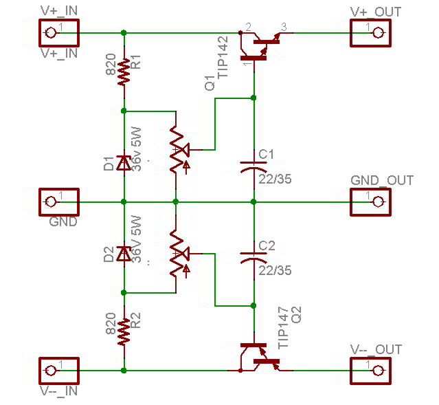
Below is a suggested circuit for a linear regulator that can be used to obtain voltages closer to +/- 30V from the high voltage rails.
It should be built on a perforated (universal) printed circuit board (not provided). The two Darlington power transistors should be mounted with their metal backs close to the edges of the pcb, to allow heatsinking. Do not operate the circuit without heatsinks except for unloaded or small-load testing.
Note that the potentiometer can lower the output voltages all the way down to zero, which is not the intended use of this circuit. This can be useful for implementing a Lab power supply, for instance, but not more than that. For any voltage lower than about 30V, the Darlington transistors will end up dissipating too much power if supplying a high power amplifier. I do not recommend using voltages lower than 30V in an actual application, so the voltage adjusting potentiometers should be kept in their upper third or so of their rotation.
Connect the V IN terminals to the switching power supply V+ and V- outputs, carefully observing polarity. Connect the V OUT terminals to the load.
Use a voltmeter to monitor the voltage between each V OUT line and GND, and adjust the potentiometers for identical voltages on the two supply rails. The potentiometers should not be touched again after this. A small drop of glue or nail polish at the base of their shafts should keep them firmly set. This circuit is not intended to allow constant playing with the output voltages.
Assuming the input voltage to the circuit is 40V, then this is what the power transistors will be dissipating as heat:
Output: 36V. drop across Q1= 4V avg current = 2A Q1 power = 8W
Output: 34V. drop across Q1= 6V avg current = 2A Q1 power = 12W
Output: 32V. drop across Q1= 8V avg current = 2A Q1 power = 16W
Output: 30V. drop across Q1= 10V avg current = 2A Q1 power = 20W
In practice, the actual dissipation values may be less than half of his, because audio signal sources vary in amplitude, with the average level being much lower than the peak levels. Also at higher currents, the source voltage (40V) will sag, decreasing the voltage sustained by the transistor.
Still, keep in mind that a power transistor dissipating about 2W of heat, gets hot enough that you cannot touch it with a bare finger.
The circuit should be protected with fuses on both output rails, and additional electrolytic capacitors should be used both before and after the circuit. The SMPS has 100uF capacitors filtering the output. If this doesn't seem like a lot, keep in mind that it's operating frequency is 100-300KHz. At these frequencies, a capacitor has filtering effectiveness equivalent to one 2000 times larger at 60Hz. You can add another 100 to 500uF of capacitance between the SMPS and the linear regulator, depending on your means, but this is not mandatory. Make sure the electrolytics are rated for a voltage higher than the highest voltage it may be subjected to. The is no evidence to suggest that over-rating the voltage of a capacitor improves performance, or lifetime, or any functional parameter. A 63V working voltage means just that: the cap can work at 63 volts. Over rate by 5-20%, but not by 100%.
On the load side, I recommend a minimum of 500uF of capacitance for every 1A of peak current draw by the load . This is 10 times lower than typical recommendations for audio amps, but keep in mind, this is not a 60Hz supply, and you are not struggling with 60Hz ripple. Plus you are using double regulation, versus most amps out there which have no regulation at all on their supplies.
To mitigate any high frequency (200KHz+) ripple on the supply, every electrolytic capacitor you add should be paralleled with 3 other caps.
A .1uf to .5 uF ceramic, a 0.01 and a 0.001 uF ceramic. This is because larger capacitors have inductance, and so high frequencies do not go into them. For the same reason, ceramics are better for this purpose than mylar or other types: they have the lowest inductance.
Keep in mind also that in most cases, audio amplifier transient response benefits from having additional supply decoupling capacitors positioned as close as possible to the output transistors. This means an electrolytic, paralleled with a .1 and a .01.
Note in the circuit above, that R1/R2 can be between 400 ohms and 820 ohms. C1 (positive rail) has its + terminal connected to the transistor base. C2 (negative rail) has its + lead going to common ground.
Enjoy your power supply!
9. Lambda SMPS schematic
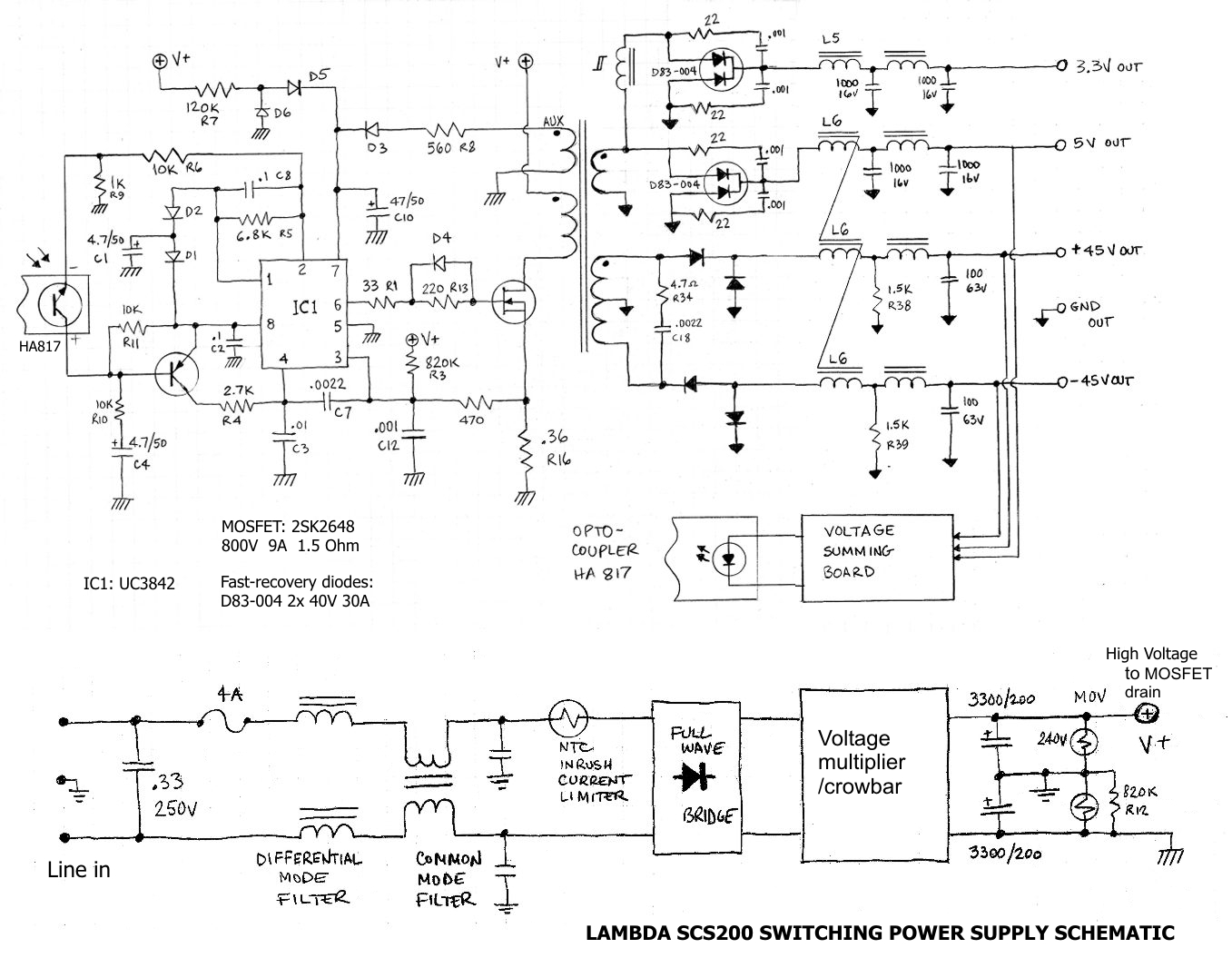
An RCD reset network connects between the MOSFET drain and the V+ line and has been omitted for clarity.
10. Making an isolation transformer.
Testing this and other switching power supplies with line powered equipment such as oscilloscopes requires powering the test equipment through an isolation transformer. This is a 1:1 turns ratio transformer, either 120V to 120V or 220V to 220V, depending on your area. You can use a transformer specified for 220/220V on 120V lines (they'll give you less power, but they'll work well and safely), but you cannot do the opposite or you'll burn the part quickly.
If you can find surplus or reasonably priced 1:1 line transformers in your area don't hesitate to buy one. They are useful for a lot of testing and experimenting. A good price for an isolation transformer in my opinion is about $20 to $30 or less.
I use a big black heavy tar-coated transformer made for old tube TV's that I bought for $1.95. It had a 260V winding, which I was able to center-tap at 130V. I scraped away the tar from the edge of the bobbin until I got to copper wires. Then I snagged out the exposed wire at the edge of the windings and tested the voltage . Found a layer on the bobbin that gave approximately 130V. Used a sharp syringe needle to connect the voltmeter probe to the wires, pushing the needle into the wire until it pierced the enamel insulation. When I found the right wire, stripped a few millimeters of enamel insulation and made a careful solder joint. Soaked the remaining wires with nail polish to cover up my mischief.
My oscilloscope needed 90 to 200V ac input ( I guess it has a switching power supply in there), so the 130V was OK. Other test equipment might need more precise voltages.
You can often get useful voltages from transformers that sell really cheap because they have no useful voltages.
Another, very practical approach to making an isolation transformer is connecting 10 X 12V transformers with their secondaries in series (primaries in parallel). If you can get these for under $3 each, then you're coming under the target price for a cheap isolation transformer. Or you connect some other combination of transformers that you can obtain cheaply in your area. Most oscilloscopes don't draw a lot of power, mine was 35W. So 1A or 0.5A 12 volt transformers are fine. Bolt or nail all 10 of them to a plywood base. If instead of hard-wiring the output for 120V, you use screw terminals to make connections between individual transformers, you can get a wide variety of voltages for other purposes from this contraption.
Connecting two or more power supplies in parallel.